Do you want to be informed on new Posts on this Thread? (members only)

S&S Swan Maintenance - Swan 41 exhaust fire
17 August 2015 - 11:26
#1
Join Date: 02 March 2007
Posts: 83

Swan 41 exhaust fire
My 41 recently experienced a minor fire caused by an overheating exhaust system. The boat was on charter, and the sea water filter became blocked, possibly by a jellyfish being sucked in. There was sufficient cooling water to cool the engine, as no over temperature warning occurred, however not enough to cool the exhaust.The part of the exhaust that passes under the step to the aft cabin became hot enough to set fire to the surrounding woodwork. Luckily I had fitted an automatic clean agent fire extinguisher in the engine box. This went off, extinguisher the fire, but also stopped the engine. The charterers had no idea what had happened, so they called for help and were towed in by the lifeboat.
I have owned the boat for 8 years now, and have always noticed that the part of the exhaust pipe under the step got quite hot, in fact the step was usually warm. It seems that in normal use that part of the exhaust system, which comprises two sections of stainless pipe separated by a flexible stainless bellows, is cooled sufficiently by the water cooled coaxial pipes that come from the engine, and lead to the exhaust trap in the cupboard.This seems quite a strange arrangement, and not totally satisfactory. I assume that the bellows is essential to take up the vibration of the engine, however it would be better if there was some way of cooling this.I intend to fit a surface mount temperature switch to this part of the exhaust to provide a warning in future, however I do not know what would be a reasonable maximum temperature for the switch. The bellows gets to at least 150C in normal use.

The fire has damaged the bottom part of the wood bulkhead below the door frame, and also part of the internal GRP moulding. The hull moulding seems untouched, so I will clean up the area and repair it with epoxy and glass cloth as best I can.

I would very much like comments from other 41 owners, and of course, the professor.

Cosmo Little (Trinket)

17 August 2015 - 15:53
#2
Join Date: 02 January 2008
Posts: 1547

Dear Cosmo Little
Sorry to hear about this.
The Swan 41 exhaust arrangement was conceived before the days of wet exhausts, and originally there was a heat resistant red rubber hose between the engine and the exhaust pot in the cupboard. Guess there are not many original hoses any more.
It appears the steel parts are a later installation. Are both steel tubes in the photo water cooled, having double concentric walls with water in between?
It is suggested you consider a wet exhaust with a rubber hose cooled by water injected in the exhaust bend. Can be routed in the same way to the cupboard, but there needs to be a water lock with sufficient capacity to contain the water flowing back from the high point, and it needs to be in line with the exhaust bend so water can not flow back into the engine at large angles of heel.
With wet exhausts there should be a temperature switch on the exhaust bend, set to alarm at about 125 deg C. The max dry exhaust temp for Perkins 4-108 is 670 deg C.
If you could confirm which engine there is, and the hose diameter used with the water injected exhaust bend I can provide more advice for the water lock. A siphon break arrangement is also necessary for the cooling water circuit.
Kind regards
Lars

18 August 2015 - 10:49
#3
Join Date: 02 March 2007
Posts: 83

Dear Lars,

Thanks for the reply. I have looked at the original drawing for the exhaust system, and can see where the rubber hose was connected. In my installation the s/s pipes to the right and left of the bellows flanges have , I think, been welded to the stubs where the rubber hose connected.These pipes are not water cooled.
I have now found a post where this topic has been previously discussed, and it seems other boats have adopted a similar arrangement with a flexible s/s bellows. In my situation there was no attempt to protect the surrounding woodwork with metal plates. I think that if the passage under the step was fully lined , then the fire would not have occurred.
Although a water cooled exhaust would be preferable, there is nowhere to place the conventional water trap, and still use the large mixing box in the cupboard. I think that I will keep the same basic arrangement, as the stainless parts of the original exhaust, ie the engine manifold connection and the mixing box are all very substantially constructed and in good condition.
A rubber connecting pipe would in many ways be preferable to the replacement s/s connection. Is there no modern material that can survive the high temperatures?

best regards

Cosmo Little

18 August 2015 - 10:53
#4
Join Date: 02 March 2007
Posts: 83

PS

Dear Lars,

If you know of an installation where a water lock has been fitted, I would certainly consider this. Would one need a new exhaust manifold connector?

Cosmo Little

18 August 2015 - 19:17
#5
Join Date: 02 January 2008
Posts: 1547

Dear Cosmo Little
Pls see the Forum thread dated 10 Aug 2010 for a water lock. A rectangular shape with smaller dimensions would be preferable, the size is dependent on the routing to the thru-hull. The existing arrangement requires less volume.
A new exhaust bend with water injection is needed.
Kind regards
Lars

21 August 2015 - 09:31
#6
Join Date: 02 February 2007
Posts: 202

Hello Cosmo Little.
On our 41 we had the original "heat resistant" pipe when we bought it some 30 years ago. It kept burning and after trying to have a new one unsuccessfully we went for the arrangement you will see in the picture. It has been in operation for a few years without problem as long as there is sufficient place for the flexible tube lengthwise. (The first try had this pipe too compressed longitudinally and it broke after two years.)
This type of flexible pipe (50mm diameter) is the same as used on lots of trucks in the US and is an american product.
As you writ,e I also manufactured a lining around the space under the step.
One point which was mentioned to me by Lars at the time I was trying to find a solution, is that you must make sure that all the air suckded by the engine should be used to cool the pipe, I.E. flow around it. To do so you have to increase as much as possible the size of the passage of the exhaust pipe, and close the ventilation of the engine box.
Kind regards.
Philippe 41/022

21 August 2015 - 09:38
#7
Join Date: 02 February 2007
Posts: 202

Dear Cosmo Little,
This is the picture taken after my first installation. You can see that the flexible pipe is too compressed longitudinally.
Junctions to the exhaust pipes, and muffler, are from the same supplier.
Second thing you will notice on the right side of the picture is that I have been putting some anodes in the small pipes designed to purge (empty) the water lining of the muffler. (See small electric wire). No holes since...
Regards.
Philippe 41/022

26 October 2015 - 10:43
#8
Join Date: 02 March 2007
Posts: 83

Dear Philippe,

now that winter is here I have started to make a proper repair of the damage. Your picture is very useful. I think that it is a good idea to carry the water in a metal tube as you have done, as it provides extra cooling of the flexible section. I will keep my stainless bellows as it seems in good condition.
Do you know how to remove the large mixing cylinder in the cupboard?

regards

Cosmo Little

26 October 2015 - 11:04
#9
Join Date: 02 February 2007
Posts: 202

Dear Cosmo Little,
With the original configuration of the exhaust it should go out through the opening above the kitchen cupboards. For this to be possible you have to dismantle not only the door itself, but also the frame. This should not be a problem as everything is screwed, and ther is no glue whatsoever.
In your case, I am not sure what will happen with the flange which seems to be welded to the tube.
You might have a look at this site: vente@silencair.com which could show you various possibilities. This is where I bought my flexible exhaust.
All the best.
Philippe 41/022

10 April 2016 - 12:52
#10
Join Date: 02 March 2007
Posts: 83

To finally conclude this post, please see photo of completed repair. A new bellows has been fitted, as the old one had numerous pin holes. Also a new over temperature sensor attached to the water jacket. This operates at 90degC, a temperature which very soon would be reached if the cooling water failed. The entire area is lined with fibreglass tape and copper sheet. The bellows gets to a temperature no higher than about 120degC in normal operation.

Cosmo Little
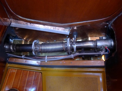
  • Threads : 1702
  • Posts : 10217
  • Members: 820
  • Online Members: 0