Do you want to be informed on new Posts on this Thread? (members only)
| S&S Swan Maintenance - Engine Alignment Issue |
|---|
|
Join Date: 27 January 2011
Posts: 140 |
||
|---|---|---|
|
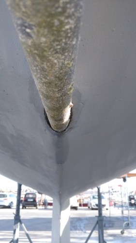
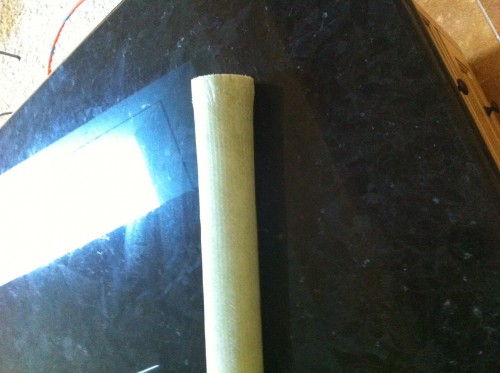
Engine Alignment Issue Last fall we discovered a water leak in the area of the stern tube of our 411. We could fix it temporarily with the help of a bicycle tube, the plan being to have a closer look at it when the boat got out of the water for antifouling. Long story short, as can be seen on the photos, the drive shaft is not centric in the stern tube, and there has been friction between the drive shaft and the tube. The tube needs to be replaced, maybe also the shaft. It turns out that if the engine is lifted into the correct position, with the shaft then being centric in the tube, the engine does not fit under the wooden box anymore. I assume that this already became clear when the engine was built in under previous ownership in 2007, and that it was then lowered to fit into the box. It still passed through the tube, and the gasket in the shaft bracket also seemed to have accepted this, no dammage to be seen there. In 2012 the silentblocks were changed and the engine realigned while the boat was in the water. I assume that this then resulted in the situation we have now. The engine is a Nanni 4.220.HE with 50 HP. We currently only see these two options to fix the issue: 1. replace stern tube, and repeat the 2007 compromise 2. replace stern tube, build custom plaques for the silentblocks which are too short, place the engine in the correct position, increase height of the engine box, shorten the ladder Did anybody have a similar issue? Are there further solutions? Thank you in advance for any advice.
Christian IF 411/028
  |
|
Join Date: 02 January 2008
Posts: 1547 |
||
|---|---|---|
|
Dear Christian Sorry to hear about this.
When the shaft touches the stern tube this creates a lot of noise, and you must have wondered what is going on.
You could also consider shortening the shaft strut slightly, or recessing its upper end more into the bottom laminate, adding the corresponding thickness of laminate on the inside. There should be sufficient clearance between propeller and hull to allow this.
Where is the leak, and what material is the stern tube? Originally it was stainless, but GRP recommended, lasts longer.
Are there marks on the shaft? Checking of its straightness is a necessary operation here, and if this can not be done properly shaft replacement is due.
Kind regards
Lars
|
|
Join Date: 27 January 2011
Posts: 140 |
||
|---|---|---|
|
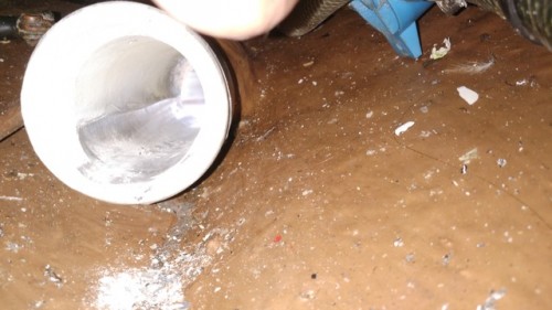
Thank you Lars! We heard some noise when using the motor when there were high, short waves, but this was ever since we have the boat and we did not consider it alarming. Also, the boat had been in a yard in 2011 shortly after we bought it, to install a PSS. At that time, the shaft was also put onto a turning machine. The material is stainless. The white look on the photo comes from salt deposit. There seems to be a small crevice at the bottom of the tube. I have not been back in Marseille yet to look at the issue in person. The shaft can potentially be saved (there are some marks but they do not look dramatic), but must go onto the turning machine again, as you say. Shorting the shaft strut is an option we have not thought about yet - I will bring it up! I assume bronze would also be a good choice for the tube? Christian
|
|
Join Date: 02 January 2008
Posts: 1547 |
||
|---|---|---|
|
Dear Christian A stern tube of bronze is also a good alternative, but you must make sure that it really is bronze and not brass. The materials look the same.
If you replace the stern tube you can move it slightly down, so the shaft is centered with the engine near its lowest position.
If the leak is between the stern tube and the surrounding GRP, a temporary fix is to drill a hole into the GRP right to the stern tube surface, at about halfway the glassed in length, and inject epoxy into the hole until it flows out each end.
Assuming that the reduction gear now is in-line, there is one more alternative - change the gear to one with down angle, and cut down the engine bearers so they fit the new nearly horizontal engine position. This is a quite costly and laborous way.
Kind regards
Lars
|
|
Join Date: 15 April 2011
Posts: 395 |
||
|---|---|---|
|
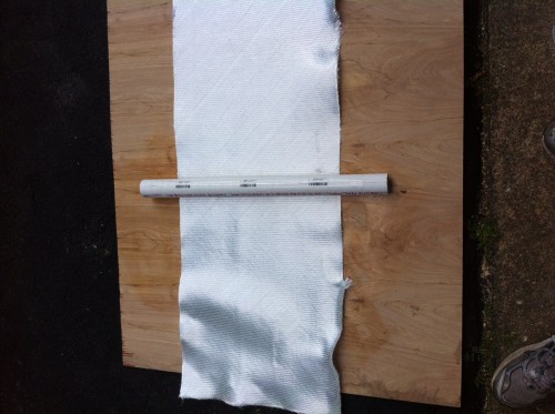
Dear Chris, I am in the process of replacing the drivetrain on my boat and one component is a new stren tube. I frabricated one using West System Epoxy and 17 oz. biaxial fiber glass. I have pictures if you think you will make a new one yourself. It was quite easy. Fair Winds, Chris Mabel's Casse Tete 003/43 |
|
Join Date: 27 January 2011
Posts: 140 |
||
|---|---|---|
|
Hi Chris, it turns out that the only solution the mechanic proposes is GRP for the tube, as recommended by Lars. Can you post a photo of your solution here? In the meantime I have found older photos of our boat when it was on the hard, which clearly show that the shaft was in the center of the tube. Not clear yet, but it could be that it is only the noise isolation I put into the box which prevents the engine from fitting when it is correctly positioned. I will be on the boat in 10 days and then see for myself. Problems like this are part of the fun, especially once they are solved. Thank you, Christian IF 411/028 |
|
Join Date: 27 January 2011
Posts: 140 |
||
|---|---|---|
|
In the meantime, the engine has been correctly aligned, which required placing each of the the silent blocks on a pedestal so that the engine does not sit too high up on the silent block screws. Another error corrected from the initial installation of the machine is to have two countered nuts on the silent block screw below the engine mount, and one above, instead of the other way around. Due to lack of time, the stern tube is not replaced yet. The crevices were filled so that it is watertight, replacement is planned for the winter. The engine now runs much better than before - vibrations are very much reduced. I started to replace the rotten 1978 engine noise insulation inside the engine compartment with modern material (not easy given the limited space). The job is only half done, but the result is already promising. Fire-proof foam will be used on the noise bridges where tubes traverse the compartment. Christian IF 411/028 |
|
Join Date: 15 April 2011
Posts: 395 |
||
|---|---|---|
|
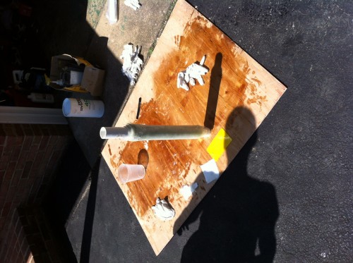
Dear Christian, I see that I missed a request from you...I apologize. I don't know how that happened so if you have questions and don't hear back, please send me an email. Building the stern tube was easy. The Professor determined the material and thickness of the tube for me - that's the hard part. I knew i had a 1 1/4 inch shaft to fit and discussed with Lars the size of the opening - bigger was better for me. Then I determined if I could find a dripless seal that matched the outside diameter of the tube and the 1 1/4 inch shaft diameter. Once I was secure in all of my dimensions, building the tube was very straight forward. I purchased a pvc pipe that was slightly larger than my inside diameter dimension; the difference between the pvc OD and the specified ID of the stern tube is the kerf of the saw blade that is used to cut the tube in half and then in quarters. This cutting into quarters is done to allow the removal of the mandrel (pvc pipe) from the newly formed stern tube. On a band saw, I cut the pvc pipe on center 3/4 of its total length, alenght still greater than the length of the stern tube. I inserted spacers in the newly sawn kerfs and taped the to pipe tightly so that I could make the second cut, 90 degrees from the original. When finished, I made one final cut across the pvc pipe to remove the portion of the pipe that was not cut. Finally, I removed the tape and was left with 4 quarters of the pvc pipe which were then taped together carefully to form a round tube. The purpose of this effort is to allow the pvc pipe to be removed from the newly formed grp stern tube. I think you may be able to skip this step and purchase any tube that has the correct outside diameter and carefully tape the outside with packing tape. Removal will be done with a hammer! Hit the pipe on edge to free it from the inside of the newly formed grp stern tube. Once you have your mandrel, pvc pipe cut or some thing else, tape carefully with packing tape. Using 17 ounce biaxial glass and west system epoxy, my son and I wrapped a continuous piece of fabric around the mandrel while applying epoxy. When finished, I cut out the pvc pipe and had my new stern tube. I'm looking for Please write if you have questions! Chris Mabel's Casse Tete 43/003
   |
|
Join Date: 27 January 2011
Posts: 140 |
||
|---|---|---|
|
Thank you for the photos Chris! Replacement of the tube is a project for the coming winter. It looks like the person who is doing the work for us has a source for these tubes, but I found it interesting from your post how easy it is to build them yourself!
Christian |
|
Join Date: 27 January 2011
Posts: 140 |
||
|---|---|---|
|
To close this out, this spring the old tube was cut out, a one-to-one copy was made, again in stainless steel, and laminated into the hull. The propellor was sent to MacProp and renovated there, the shaft checked and found to be ok, all seals replaced. Since our propellor blades were shaky, they would vibrate especially when waves came from the side. This created a lot of noise through resonance in the hull. Now all is perfect - there are no more vibrations, and obviously no more water coming in through the tube. This was done by a competent company in the Follonica area in Italy. They also added an electrical bronze ground plate to connect the lightning protection, which was previously screwed to the tube. Christian 411/028 IF |
- Threads : 1715
- Posts : 10273
- Members: 823
- Online Members: 0