Do you want to be informed on new Posts on this Thread? (members only)
| S&S Swan Maintenance - Stuffing around rudder post - Swan 47 |
|---|
|
Join Date: 26 March 2008
Posts: 69 |
||
|---|---|---|
|
Stuffing around rudder post - Swan 47 Hello Forum.
On our trip across the Atlantic, we developed a leak from around the rudder post. Popular opinion believes the stuffing needs to be replaced. I am looking for input on the following:
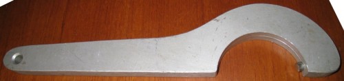
1. What is the technique to replace the stuffing? 2. Does it require a haul out? 3. Where does one find the tool to loosen the silver casing that contains the stuffing (see pic)? 4. What does the tool look like? (a pic would be great)
I look forward to your responses.
Cheers,
Milo s/y The Last of the Normal People 47(048) 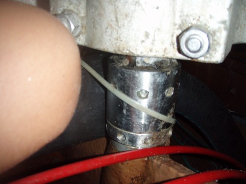 |
|
Join Date: 02 January 2008
Posts: 1547 |
||
|---|---|---|
|
Dear Milo Pls look at previous contributions within this thread. Your questions: 1. Described previously 2. Haul out not needed 3. A tool was originally delivered with the yacht 4. See earlier contributions The size of your seal is 3/16 inch Kind regards Lars |
|
Join Date: 21 May 2007
Posts: 73 |
||
|---|---|---|
|
Dear Milo,
|
|
Join Date: 31 January 2007
Posts: 52 |
||
|---|---|---|
|
Dear Milo,
 |
|
Join Date: 26 March 2008
Posts: 69 |
||
|---|---|---|
|
Hey Guys. Very helpful as always. Lars, I cannot find the other forum sites, would you send me a hyperlink, please? I am sure they are there. Sergio, you have given us the confidence to tackle this project. Jyrki, we are now well aware of what we need to use and can order on-line. Thank you all. Milo |
|
Join Date: 02 January 2008
Posts: 1547 |
||
|---|---|---|
|
Milo Here the URL addresses of interest: http://www.classicswan.org/forum/post_thread.php?thread=427 http://www.classicswan.org/forum/post_thread.php?thread=396 Suggest you take a look at the various contributions, there are over 6 pages of threads on various subjects Lars |
|
Join Date: 29 January 2007
Posts: 1033 |
||
|---|---|---|
|
Dear Friends, 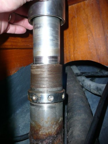 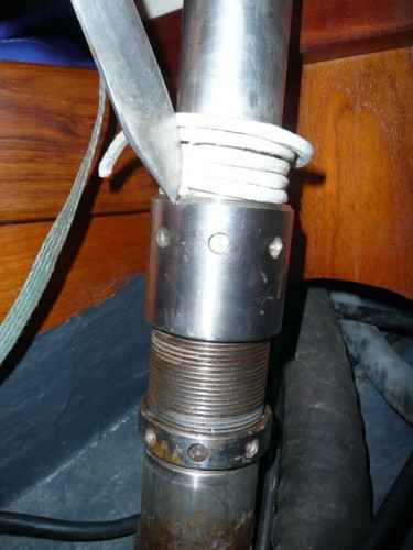 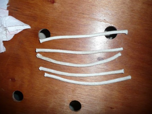 |
|
Join Date: 29 January 2007
Posts: 1033 |
||
|---|---|---|
|
Ref. parts for UASG tool is: 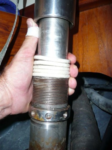 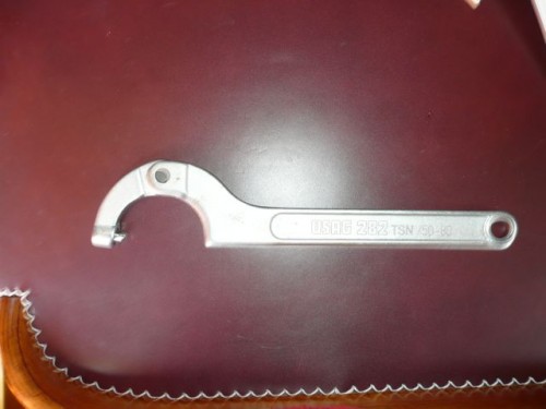 |
|
Join Date: 26 March 2008
Posts: 69 |
||
|---|---|---|
|
Dear Helpful Friends.... If you look at my original post and also the picture below, you will note the design of the Swan 47 does not allow for the same amount of wiggle room (or ability to lift) the gland. The quadrant sits almost on top. Is it still possible to do this as you have described or is there something extra or special I need to know? Cheers, Milo 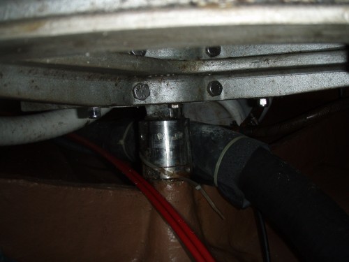 |
|
Join Date: 02 January 2008
Posts: 1547 |
||
|---|---|---|
|
Milo You are right that the quadrant is too close to allow the gland to be lifted high enough. There is a square portion on the rudder stock for the quadrant, check if it is long enough to allow the quadrant to be raised sufficiently after partly loosening its bolting around the stock. The upper rudder bearing is the next item restricting the distance the quadrant can move upwards. If the quadrant can not be raised high enough it has to be removed from the stock. Make sure the new packing stack stays on the round part of the stock below the square portion. When putting the quadrant back it has to be aligned carefully with the grooves in the sheaves forward, and the steering wire tension checked. The wires should be hand tight, tensioning them too much makes the steering stiff. If the steering wheel has a King Spoke marked according to Rod Stephens recommendations, adjust the wires so the rudder is on the centerline when the King Spoke is straight up. Lars |
|
Join Date: 26 March 2008
Posts: 69 |
||
|---|---|---|
|
Lars and company: Well, we are up on the hard at the moment still trying to resolve our leak around the rudder post. This issue was not resolveable in the water. Today we were hauled. After some issues, the quadrant was removed and an attempt to drop the rudder was performed. The workman state they need to remove the bottom section of the skeg to remove the rudder (see pic). The skeg bottom, made of bronze, had been thickly fiber glassed over. It also appears to be cemented on as well. There has been much effort to remove this section, so much so I am worried there may be a missing piece of vital information for removal. Their feeling was it is not wise to fiberglass this section. What is the secret to the removal of the bottom section of the skeg? Any comments or suggestions are appreciated. Milo 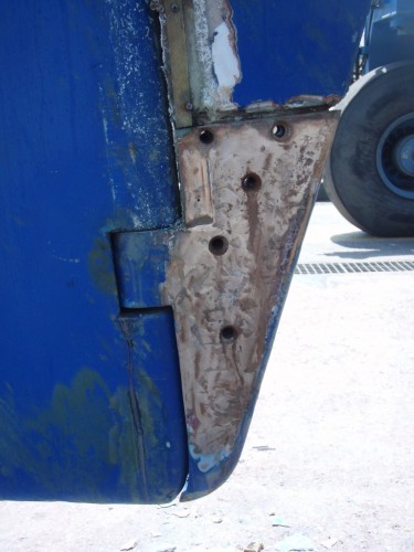 |
|
Join Date: 02 January 2008
Posts: 1547 |
||
|---|---|---|
|
Milo The bronze skeg shoe was not fiberglassed over originally. The recommendation for getting it off is to apply some judicious heating and hitting, but put a support under the rudder before attempting this, the rudder including shoe will fall to the ground when the shoe lets go. Do not heat the shoe over 60 C (140 F). When re-installing the shoe it has to fit tightly onto the GRP skeg, and new screws about two inches longer are required, so they can be tightened very hard from the threaded end with a big wrench, and the threads finally securely locked. Lars |
|
Join Date: 25 July 2008
Posts: 30 |
||
|---|---|---|
|
Dear Lars, We have the same problem. We took the quadrant off and were able to lift the gland but the round section of the stock is not long enough and so the packing come on the square portion. The yard recommends to cut a piece of the screw part to �gain� some round stock. We are confused and do not know what to do. Thanks for your help Ludovic of RUMTRADER Swan 47 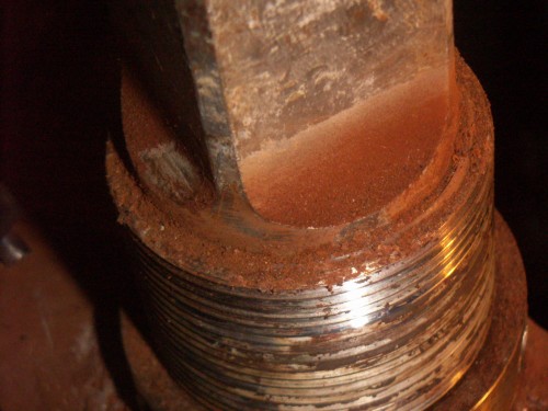 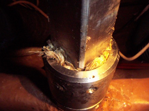 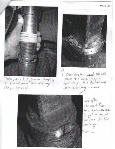 |
|
Join Date: 26 March 2008
Posts: 69 |
||
|---|---|---|
|
Ludovic: We finally arrived at a solution after many days in the boatyard and the solution has been effective thus far. However, we cannot vouch for the long term fix. Lars (the Professor) also gave us several other options which I will attempt to summarize, but we had time constraints such that we could not pursue them. We also had a very short "round" bit of rudder post for the packing to be placed on, though perhaps a bit more than it looks like you have. With the boat hauled out, it appeared as though rudder had settled down, effectively shortening the height of the post protruding up through the hull and rudder stock casing (the male threads of the gland). We attempted to have the skeg shoe removed in order to drop the rudder post, and allow replacement of the washer between the bottom of the rudder and the top of the skeg shoe. This proved a futile effort, and ultimately the boatyard fashioned a two-piece bronze washer (see pic of one half ) that they fit around the post, between the rudder and the skeg shoe (see pic), effectively elevating the rudder 1/4 inch (not much) thus giving 1/4" more "round" post for packing to go around. The yard then placed packing and resealed the gland. We didn't leak in the passage from There is a plastic washer at the skeg shoe protrusion that is what likely "wore away", and was replaced by the bronze washer the boatyard fitted, that may be replaceable if you can remove your skeg shoe. Despite great, even violent effort, the skeg shoe did not want to come off. Lars also suggested: That the ends of the packing band ring are cut with a long tapering overlap instead of straight off, due to the limited area for packing. Using a thinner packing and more turns may also work. If the gland bottoms on the outside locking ring before it compresses the seal, it would be advisable to put in a filler piece at the top of the gland recess. An alternative way of fixing the problem is to shorten the rudder stock casing, i.e. the threaded tube coming through the hull, but this requires its removal. Had we been able to remove the skeg shoe, and thus drop the rudder, Lars suggested that raising the rudder to allow ~10mm of stock above the rudder casing "This would be sufficient for an O-ring used as a seal around the shaft. The O-ring can not seal against the threads, requires a bushing inside them, with a flange above for compressing the O-ring a suitable amount. This needs to be worked out in detail if you choose this route. Alternatively a lip seal could be used." "The other possibility is to raise the rudder approx 25 mm in order to use the existing packing band seal. This requires that the top of the blade is cut down this amount. Also the bottom of the skeg needs to be shortened so the bronze shoe can move 25 mm higher up" We hope this is helpful. Jill and 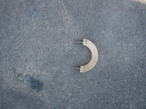 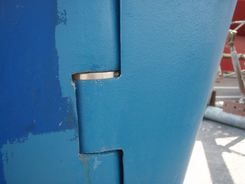 |
|
Join Date: 25 July 2008
Posts: 30 |
||
|---|---|---|
|
Dear Thank you for sharing your very useful experience. We have checked if we could lift the rudder and gain some round section on the rudder stock. As you see on the picture we could probably only gain a few mm and we need cm. I cannot see what could have moved/changed since the boat was build. During the last summer we took around I cannot understand how the original setting was, I am confident Nautor has thought of a solution but so far I do not have it. Any suggestions? 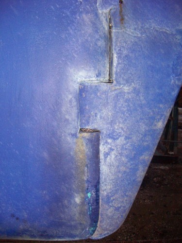 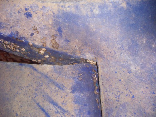 |
|
Join Date: 02 January 2008
Posts: 1547 |
||
|---|---|---|
|
Dear Ludovic Thank you for sending the reminder, otherwise your post would have gone unnoticed. Milo's message mentions earlier suggestions, an additional one is to clamp a flexible neoprene gaitor around the casing, and around the rudder stock just below the quadrant to keep the water out. The gaitor has to allow 35 degrees of rudder angle each side. For example Lewmar show gaitors in their catalogue, also JP3 should have them. In this connection I would like to ask where the upper end of the rudder stock is in relation to the upper end bearing sleeve? The sleeve sits in the fitting attached to the cockpit floor, and the position can be inspected if you open the emergency tiller screw cap in the cockpit. Removing the upper bearing assembly probably allows the gaitor to be slid onto the rudder stock. Best regards Lars
|
|
Join Date: 06 June 2008
Posts: 6 |
||
|---|---|---|
|
Lars and Ludovic, In the course of our repairs, we had the emergency tiller access open, the solution of a 'gaitor' certainly seems feasible given the set up have if memory serves me correctly (i am unfortunately currently separated from my boat by an ocean!). Milo and I will definitely keep this in mind if (when) we begin to leak again... Jill s/v The Last of the Normal People
|
|
Join Date: 06 June 2008
Posts: 6 |
||
|---|---|---|
|
Lars, Have gone to the Lewmar website, looking for gaitors/gaiters with no success. Can you give any more guidance, or better define who/what "JP3" is? Thanks, Jill s/v The Last of the Normal People |
|
Join Date: 26 March 2008
Posts: 69 |
||
|---|---|---|
|
Hey Guys: Our emergency tiller screw cap was jammed solidly in place. We asked many people for suggestions on how to remove it. After attempting all manner of things, we finally gave up and had it cut away and a replacement one made (out of Teflon I think). It was an ordeal. Milo 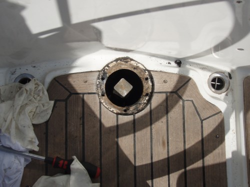 |
|
Join Date: 02 January 2008
Posts: 1547 |
||
|---|---|---|
|
Jill The printed Lewmar catalogue 2006/7 shows gaitors on pages 215 and 216, but it appears the on-line selection today does not. JP3 is the major steering system manufacturer in France, see jp3steering.com. They do not show gaitors on the website, but are likely to make them. You can have your own gaitor made of neoprene rubber by the suppliers above, or at a rubber shop. For this you need the length and the circumference at each end. It must be flexible enough to allow the rudder to turn. Two hose clamps also needed. Kind regards Lars |
|
Join Date: 02 January 2008
Posts: 1547 |
||
|---|---|---|
|
PS Would not consider the gaitor a permanent fix. The rudder stock casing needs to be shortened or dropped to unhide more of the round stock. It looks like the casing could come out through the cockpit floor. Pls note that the casing has bearing bushings of plastic each end, they need new machined recesses if the casing is shortened. The upper bushing is end stop for the seal when it is compressed by tightening of the sleeve. Lars |
- Threads : 1715
- Posts : 10273
- Members: 823
- Online Members: 0