Do you want to be informed on new Posts on this Thread? (members only)
| S&S Swan Maintenance - Engine insulated negative earth / insulated return |
|---|
|
Join Date: 21 April 2021
Posts: 18 |
||
|---|---|---|
|
Engine insulated negative earth / insulated return I have read elsewhere in the forum that our boats were originally equipped with a insulated negative earth for the engine electrical system. I understand that this is to isolate the engine block from the negative circuit and connect the negative just to the starter during starting. My Perkins M65 was available with the option of such an insulated return but from what i can see it has not been fitted. I am looking for help to understand the importance of such an installation to be able to decide if i should retro fit one. Thanks in advance. dav |
|
Join Date: 30 January 2007
Posts: 461 |
||
|---|---|---|
|
I know that this is a subject which is seldom explained well so I will try to behave as an as-clear-as-possible teacher. It is a good practice that all currents, in normal condition, are conveyed always and only through appropriate and properly sized wires and cables, i.e. it is NOT a good practice to have currents flowing through metal parts like engine components, metal frames or whatever. I repeat: in normal condition. There are are reasons for this but the most understandeable is that in this way all currents are, at any time, easily traceable. On the other hand it is also a good practice to have all metal parts, where current is not supposed to flow, connected to a common ground, the same for everything but, as stated above, with no whatsoever current flowing in normal working condition. There is no contraindication if also the negative of the battery is connected to this ground; on the contrary, it is perfectly ok but the reason for this is more complicate and I prefer not to discuss it here. The above is a good practice but often neglected for a narrow-minded economical reason: saving the cost of a second wire! In old cars and motorcycles the absence of the negative wire is very common, in new cars where plastic parts are very common it is less and less common. As I see it, there is no excuse for boats where stray or galvanic currents may be disruptive. Daniel, Luna Menguante 411/004 |
|
Join Date: 02 January 2008
Posts: 1547 |
||
|---|---|---|
|
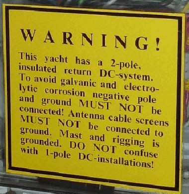
Dear dav A 2-pole insulated system prevents leaks in the negative circuit from going out in the water through the engine and shafting, and causing electrolytic corrosion to underwater parts.
It is suggested that you study the original electrical schemes. I think also the starter was originally fully insulated, the described arrangement is a later addition, but is ok.
All the various sensors on the engine need to have their negative insulated from it, as well as the alternators. If the original alternator gives up, it is often replaced with a cheaper car alternator, which is not insulated.
Is there a switch labelled ALTERNATOR OFF on the switchboard? I can explain the purpose if required.
Appended the original greetings from the yard electricians
Kind regards
Lars
 |
|
Join Date: 21 April 2021
Posts: 18 |
||
|---|---|---|
|
Dear Lars and Daniel, Thank you for your input. I now understand that the importance of the insulated negative return is to avoid galvanic corrosion. The previous owner had a problem with galvanic corrosion in the fuel tank after he installed a fuel gauge so i am very aware of the problem. I have seen that on modern Beneteau's there is a main cut-off switch also on the negative circuit and understand that it may be for similar reasons. The wiring of our Swan is not completely original, the main panel has been changed, the aft/cockpit panel has been disconnected and the main cables from the batteries have been changed; however the bulk of the distribution wireing is original and i have traced the circuits and matched them to the wire codes in the original plans. The alternator off switch is no longer present. I read elsewhere on the forum that this is to avoid radio interference but i dont have plans to install an SSB radio. The starter on the M65 is probably not insulated which is probably why it requires the power relay to convert to an insulated return system. The other sensors however seem to be insulated. I shall be changing the alternator to a Balmar with isolated ground and external regulator. Following both your suggestions i will pursue changing to an insulated negative return. Perkins no longor provide the insulated return kit so i will need to source the parts. Currently there is a negative lead directly from the negative bus-bar to the engine block. Once this is connected to the mentioned relay I imagine that i will need to ground the engine to the keel? Warm regards, dav |
|
Join Date: 02 January 2008
Posts: 1547 |
||
|---|---|---|
|
dav Thank you for the information
This may be considered nit-picking. but an electrical leak through the engine and shafting causes electrolytic corrosion, which may sometimes cause the opposite effects cpmpared to galvanic corrosion.
Galvanic corrosion requires two dissimilar metals in a conductive medium, and diesel oil is not conductive, so there was another reason in the fuel tank. Maybe plenty of water in the fuel?
A negative main switch is a good thing, if you turn it off when you leave the boat there is no way electricity can leak out in the water.
Interference had to be avoided for old time radio direction finding, which does not exist any more.
Originally there was a lightning protection system connecting the mast, stays, and main shrouds plus the engine to the mast step, and you should check if the engine already is connected. Pls note that this system has to be completely separate from the electrical system
Kind regards
Lars
|
|
Join Date: 30 January 2007
Posts: 461 |
||
|---|---|---|
|
I am very sorry to contradict that nice poster of the Nautor electricians and it is very far from my intentions to be argumentative but in the original electrical drawing of my boat (411), the negative of the battery is indeed connected to the ground. I also happen to have the original drawing of a 41 (earlier than mine) where the negative is NOT grounded indeed. Please notice: in the 411 the full electrical circuit would perfectly work if there was no connection to the ground and this is the very important issue over which we all agree. Moreover, also of paramount importance, there is one and only one connection to the ground very close to the battery, i.e. in only one point of the drawing, that symbol (a striped triangle) can be found. I would add that in a well maintained DC electrical circuit where all its elements are strictly two-pole, that single point grounding would never cause any stray current. This is true if we neglect a possible AC additional circuit but this is a bee-nest I do not want to uncover! As I tried to hint in my previous post, connecting the negative pole to the ground is possible although it is not necessary for the functioning of the circuitry. It may sound absurd but in fact there would not be any counterindication in grounding the positive pole instead; not both, of course! The grounding of one pole of the DC circuit is something controversial and depends on the school of thought; as I see it, it is analogous to the controversial issue of "bonding" or "not bonding" and it is not very worth argueing about it. In my boat the Nautor electrical technicians decided to ground the negative pole of the battery at build time; I am just curious to understand why they changed their minds during the years. Daniel, 411/004 Luna Menguante |
|
Join Date: 21 April 2021
Posts: 18 |
||
|---|---|---|
|
Hi Daniel and Lars, First of all thank you for the clear explainations. I was aware of the differences in theory between Galvanic corrosion and electrolitic corrosion; however i mistakedly used the terms incorrectly and confuse them in practice! My main concern is with electrolitic corrosion caused by stray currents. The problem which the old owner had with the corrosion of the bottom of the fuel tank coincided with the installation of a fuel gauge, this leads me to suspect a stray current from the fuel gauge through the bilge water. Now the fuel gauge is on a switch which is kept off so I hope not to repeat the problem. With regards to the engine negative, the original wiring shows an insulated return. the existing wiring has the negative connected to the engine block. all the wiring on the engine has isolated negative wiring except for the glow plugs and the starter. i believe that the starter has a post for an isolated negative. Since I do not need to use the glow plugs i am considering disconnecting the negative from the engine block, connecting it to the starter and re-directing the negative circuits to the starter. I will then sort out the necessary relays to provide a negative circuit to the glow plugs during starting. With regards to grounding; the original wiring diagram does not indicate that the negative is grounded; it does however indicate that the shore supply is grounded. (see attached). In practice the 220v ground is connected to the 12v negative at the main panel. I believe that the 220v circuit is grounded at the shore supply but not to the keel; I will need to check to confirm. With regards to lightening protection; I dont have the original schematic drawing for this circuit; I have found cables connecting the backstay and forestay to the mast step, but not the engine. @Lars would you please help identifying where the connection to the engine or P-bracket would have been be made? Would the 220v ground have been connected to this circuit too? Warm regards, dav
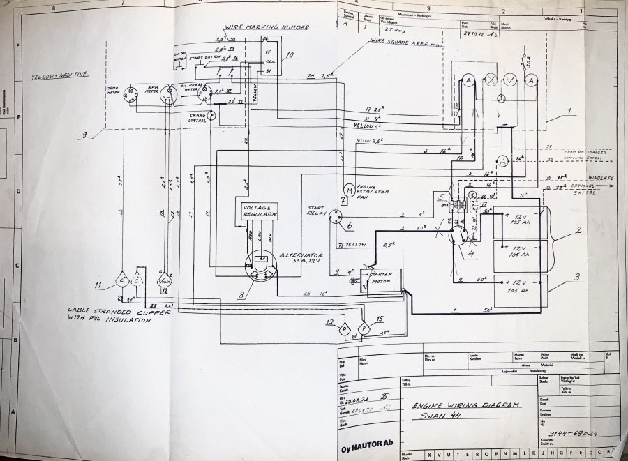 Engine wiring schematic 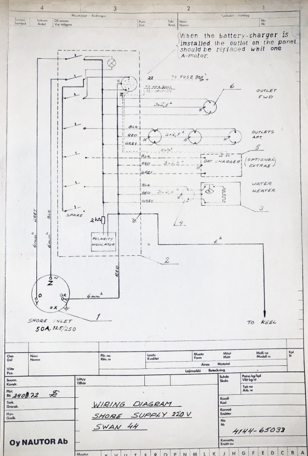 Shore wiring schematic |
|
Join Date: 02 January 2008
Posts: 1547 |
||
|---|---|---|
|
dav Thank you for the diagrams You mentioned that the engine is Perkins M65, this is a newer engine, the original was a 4.108. The P-bracket connection could be made to one of the bolts on the inside, but is not needed.
As said before no part of the electrical system to be connected to the lightning protection.
Lars
|
|
Join Date: 20 July 2020
Posts: 19 |
||
|---|---|---|
|
Nice thread you have here, so I decided to join. I have been this winter doing a new electrical panel and looking into older installations, which have been done professionally by the previous owner (or to be honest outsourced to marine electician). However I have found one contradicting thing. Bacchus has Sailor 6222 VHF radio and in its installation manual it is emphasized that it has to be connected to the ground (separate ground connection). Also in practice almost all VHF antennas connect the screen to the ground if using their mounting brackets. Now the Sailor ground has been left unconnected, and I do have some reception issues, so I'm planning to connect it now. Is it so that back in the days connecting the antenna screen to the ground would also then connect the negative pole to the ground via it? Or is there some other reason? Also Raymarine autopilot ground was left unconnected, don't know why. Br, Tapio 411/027 Bacchus |
|
Join Date: 21 April 2021
Posts: 18 |
||
|---|---|---|
|
dav Thank you for the diagrams You mentioned that the engine is Perkins M65, this is a newer engine, the original was a 4.108. The P-bracket connection could be made to one of the bolts on the inside, but is not needed.
As said before no part of the electrical system to be connected to the lightning protection.
Lars
Dear Lars, Yes the engine was replaced some 20 years ago but I still have the original perkins 4108 engine panel. Do I understand correctly that the 220V shore power should be grounded to the keel seperately to the lightening protection and that the 12v negative should not be grounded at all? Is the 220v ground meant to be connected to the 12v negative at the panel? If they are as, it is in my case, does this mean that the 12v negative is actually grounded and can be a source of stray currents? Thanks as always for your invaluable help. Kind regards, dav |
|
Join Date: 30 January 2007
Posts: 461 |
||
|---|---|---|
|
Nice thread you have here, so I decided to join. I have been this winter doing a new electrical panel and looking into older installations, which have been done professionally by the previous owner (or to be honest outsourced to marine electician). However I have found one contradicting thing. Bacchus has Sailor 6222 VHF radio and in its installation manual it is emphasized that it has to be connected to the ground (separate ground connection). Also in practice almost all VHF antennas connect the screen to the ground if using their mounting brackets. Now the Sailor ground has been left unconnected, and I do have some reception issues, so I'm planning to connect it now. Is it so that back in the days connecting the antenna screen to the ground would also then connect the negative pole to the ground via it? Or is there some other reason? Also Raymarine autopilot ground was left unconnected, don't know why. Br, Tapio 411/027 Bacchus Hi, I am sorry but I cannot be specific about the Raymarine or the Sailor you mention because I do not have any technical reference but I know very well the Neco autopilot which is a very well designed piece of electronics; I expect that other well designed devices follow the same principles. The whole electronic circuitry of the Neco is two-pole totally insulated from any of its outer metal parts. That is: the negative pole (or the positive) is nowhere DC connected to the chassis of the Control Unit or of the Motor. Notice: the phrase "DC connected" has a very clear meaning and is somehow opposed to the possibility of an "AC connection". The absence of a DC connection to ground will indeed avoid any stray current but introduces the possibility of EM (electro magnetic) noise creation and propagation which sometimes may be disruptive as well. EM noise is always created by electric motors but also by relays or by square wave electronic oscillators within the circuit; inside the Neco all three exist. In order to mitigate EM noise, there are special condensers which actually connect both the positive and the negative to the chassis and then to a ground wire; such condensers are perfect insulators for DC current but almost short-circuits for AC currents at noise frequency therefore killing the EM noise. I hope I was clear but the conclusion is straightforward: if the device is well constructed, its ground terminal should always be connected to the ground circuit of the boat and this should NOT jeopadize the keeping of the DC circuit insulated from the ground. Regarding antennas, the matter is more complicated but the principle is the same: on the antenna terminals of the radio there should not be present any DC coming from the inside of the radio. In case the antenna output/input is unbalanced, the shield of the cable should be connected to the ground of the boat because this is the way unbalanced antennas are supposed to work but... beware! ONLY if there is no DC voltage in it! In case the antenna output/input is balanced, both antenna terminals are live and should be treated accordingly. Daniel, 411/004 Luna Menguante |
|
Join Date: 02 January 2008
Posts: 1547 |
||
|---|---|---|
|
dav Has been a discussion about these things before, pls see
https://classicswan.org/forum/post_thread.php?thread=744
The conclusion was that there are different standards in use depending on the geographical location, and this affects the details.
Kind regards
Lars |
|
Join Date: 21 April 2021
Posts: 18 |
||
|---|---|---|
|
Dear Lars, Thank you for the link. I understand that your replies from that thread apply to my case as follows: 1) I would suggest that originally battery negative was not connected to ground, but nowadays there are standards prescribing this. If you have the original electrical schemes this can be checked. I confirm that the original schemes that came with my boat show that the battery neagtive is not connected to ground 2) Engine and tanks are masses of metal and could therefore be connected to ground as part of the the lightning protection system in order to prevent side flashes. My engine is connected to the battery negative, however i intend to remove this. Also in my case there is no isolation between the engine and shaft. Would you recomend that i connect to the lightening protection system? if so where is the best place to connect to? Would you recomend the same for the fuel and water tanks? There are arguments for and against the bonding of seacocks and other underwater fittings. Particularly in the USA bonding is common, but it can be pointed out that ABYC standards also contain chapters dealing with unbonded installations. Older Swans do not have bonding My Swan does not have bonding and i intend to leave it this way. 3) Shore ground should be connected to the boat ground, i.e. to the water. The shore ground often carries a small voltage which causes corrosion on underwater fittings. A protection is recommended, either a galvanic isolator, or the transformer you mention. I confirm that the original schemes show that the shore ground is connected to the boat ground (the keel). Could you please advise how this was done and where i should check to make sure it is still connected? Should the battery negatives in the main panel be connected to the shore grounds at the panel? Kind regards, dav
|
|
Join Date: 02 January 2008
Posts: 1547 |
||
|---|---|---|
|
dav 2) It is suggested that the prop shaft is insulated from the engine.
3) The grounding cable was connected to the mast step. The keel bolt nuts bear on the step bottom flange, and provide a connection to the keel.
Connect or not to connect - would suggest that you consult the appropriate standard in your area
Kind regards
Lars
|
- Threads : 1701
- Posts : 10215
- Members: 820
- Online Members: 0